
A bioswale that works starts on paper. Get the sizing wrong or the slope off, and you end up with standing water, erosion, or a soggy trench that does nothing for stormwater management. Proper bioswale design guidelines exist precisely to prevent these failures, they give you the engineering parameters, material specs, and grading details needed to build a system that actually filters and conveys runoff as intended.
At Konzept Garden, we incorporate bioswales into our landscape designs across Malaysia as part of a broader approach to sustainable outdoor spaces. Our team has seen firsthand how a well-designed bioswale can manage heavy tropical rainfall while adding real visual character to a property. We've also seen what happens when critical design details get overlooked during construction.
This guide walks you through the core technical requirements, from calculating swale dimensions and setting longitudinal slopes to selecting soil media and specifying planting zones. Whether you're a property developer planning a new site or a homeowner exploring stormwater solutions, you'll find the practical specifications and step-by-step details needed to design a bioswale that performs under real conditions.
What a bioswale is and when it fits
A bioswale is a vegetated, gently sloped channel designed to slow, filter, and convey stormwater runoff. Unlike a concrete drain that moves water as fast as possible, a bioswale uses engineered soil, plants, and controlled flow velocity to remove sediment, nutrients, and pollutants before runoff reaches waterways or recharge zones. In Malaysia's context, where intense tropical downpours are the norm, bioswales play a direct role in reducing peak flow and improving water quality directly on-site.
How a bioswale differs from a standard drainage channel
Standard drainage channels are built for speed and volume. Their job is to move water off a site quickly, often into municipal systems that are already under pressure. A bioswale, by contrast, is engineered for contact time and infiltration. Water moves through at a controlled pace, interacting with vegetation and a specified growing media layer that physically and biologically treats the runoff.
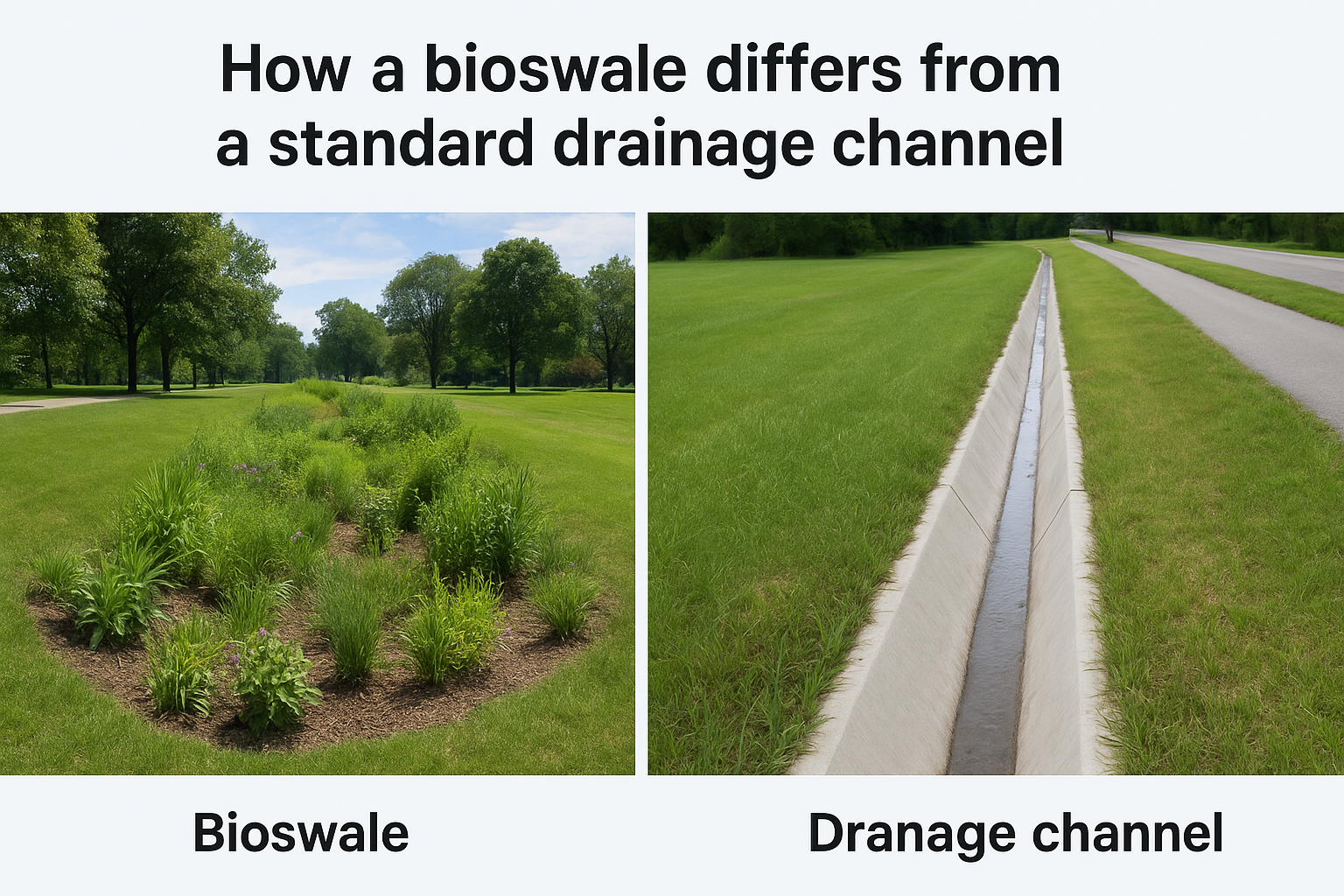
The defining feature of a bioswale is not its shape but its function: it treats water as it conveys it, rather than simply transporting the problem downstream.
This distinction matters when you apply bioswale design guidelines to a real project. A bioswale is not a soft-landscaping option you layer onto an existing drain. It requires its own cross-section geometry, soil specification, and plant palette to function correctly. Treating it like a decorative swale without addressing these engineering parameters leads directly to the standing-water and erosion problems that undermine performance.
Site conditions that make a bioswale a good fit
Bioswales perform best on sites where you have adequate linear space and a drainage catchment area that can be directed into the channel. A practical starting point is sizing the bioswale footprint at roughly 1 to 3 percent of the total impervious area draining into it, though precise sizing depends on your local rainfall intensity and water quality targets.
Your site also needs a workable longitudinal slope falling between 0.5 percent and 6 percent. Below 0.5 percent, water pools and the system turns anaerobic. Above 6 percent, flow velocity exceeds what vegetation can withstand and you get channel scour. If your site falls outside this range, you have options such as check dams to break up steeper gradients or upstream detention to control inflow on flat ground. Sites with sandy or well-draining native soils beneath the swale perform better because infiltration supplements conveyance, reducing the total volume the channel must handle during peak storm events.
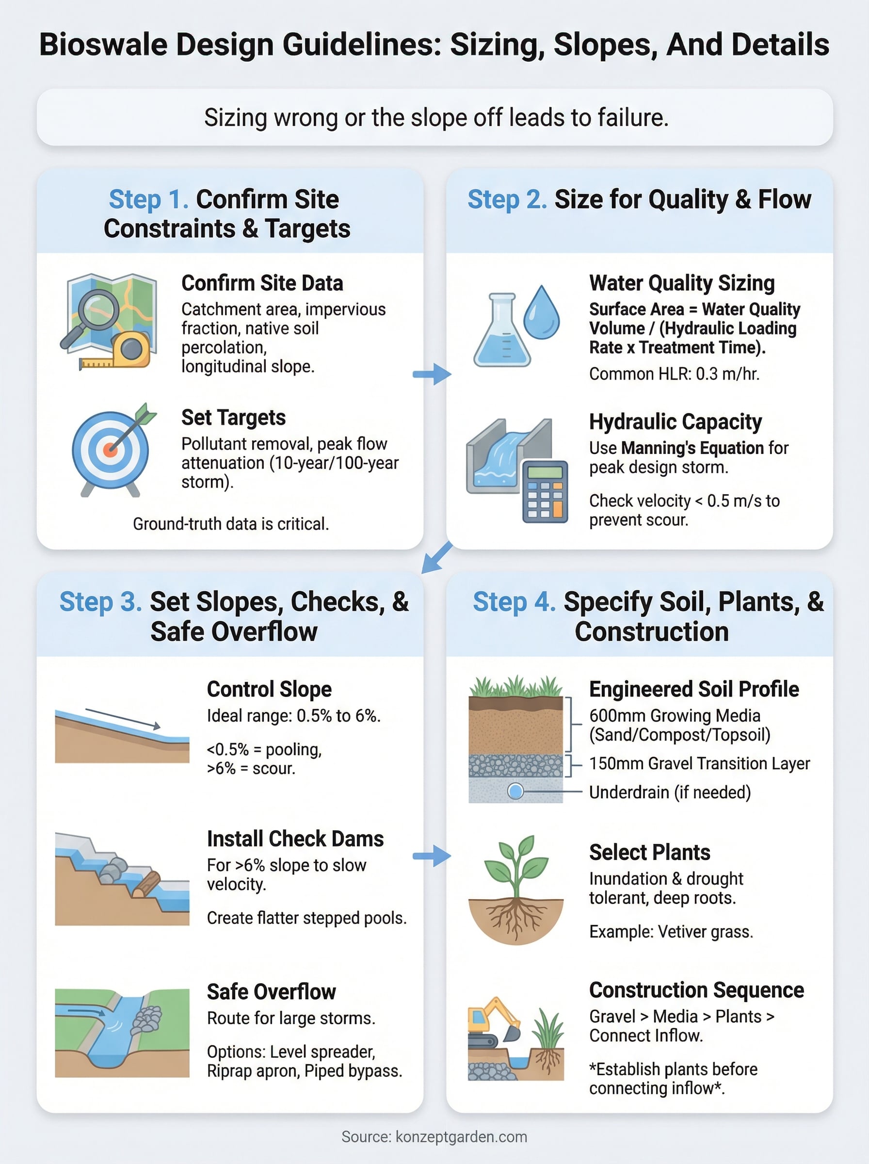
Step 1. Confirm site constraints and targets
Before you touch a design tool, you need ground-truth data from your specific site. Bioswale design guidelines consistently identify skipped site assessment as the root cause of undersized or mislocated systems. Two things define what your swale must handle: the land draining into it and the performance targets your project must meet.
Measure your catchment and existing drainage
Your first task is to delineate the catchment area that will drain into the bioswale. Walk the site and identify every impervious surface, roof, driveway, patio, and compacted path that sheds runoff toward your proposed swale location. Measure each surface and record whether it drains by sheet flow or through an existing pipe or kerb inlet.
Getting your catchment area wrong at this stage forces costly redesigns later, since every sizing calculation downstream depends on this number.
Once you have your catchment map, check the native soil conditions beneath the proposed channel. In Malaysia, soils range from well-draining lateritic profiles to poorly draining clay-heavy formations. A simple percolation test, digging a 300 mm hole, filling it with water, and measuring the drop rate over 30 minutes, tells you whether the underlying soil will support infiltration or whether you will need an underdrain to prevent waterlogging.
Set your water quality and flow targets
Your project may need to meet a specific pollutant removal target, particularly for developments subject to local planning conditions or Stormwater Management Manual for Malaysia (MSMA) requirements. Common benchmarks include 80 percent total suspended solids removal and peak flow attenuation for a 10-year or 100-year storm event, depending on downstream sensitivity.
Record these targets explicitly before sizing begins. Use the table below to organize your site data into a single reference sheet:
| Parameter | Data to collect | Source |
|---|---|---|
| Catchment area (m²) | Measured from site survey | Site plan or GPS |
| Impervious fraction | Percentage of hard surfaces | Site inspection |
| Native soil percolation rate | mm/hr from field test | On-site test |
| Longitudinal slope | % fall along proposed channel | Survey instrument |
| Regulatory removal target | % TSS or flow standard | MSMA or local authority |
Step 2. Size the swale for water quality and flow
With your catchment data confirmed, you can now calculate the physical dimensions that determine whether your swale meets both water quality treatment and peak flow conveyance requirements. Bioswale design guidelines typically separate these two checks: one sizing pass for pollutant removal and one for hydraulic capacity, and the larger result governs your final dimensions.
Calculate the required surface area for water quality
Water quality sizing sets the minimum surface area your swale needs to achieve adequate pollutant removal. The standard approach links swale area to your catchment's impervious fraction and a target hydraulic loading rate.
A common design standard targets a hydraulic loading rate of 0.3 m/hr, meaning the swale surface must be large enough to process the water quality volume at that rate without overloading the filtration layer.
Use this formula as your starting point:
Surface area (m²) = Water quality volume (m³) / (Hydraulic loading rate (m/hr) x treatment time (hr))
For a residential catchment of 500 m² with 60 percent impervious cover in Malaysia, calculate a water quality volume of approximately 15 m³ based on a 25 mm treatment storm depth, then divide by your loading rate to confirm minimum surface area.
Check hydraulic capacity with Manning's equation
Manning's equation confirms that your sized channel can convey the peak design storm without overtopping. You need three inputs: the swale's cross-sectional area, hydraulic radius, and Manning's roughness coefficient, which for dense grass cover typically falls between 0.20 and 0.35.
| Input | Typical value | Notes |
|---|---|---|
| Manning's n (grass) | 0.20 to 0.35 | Higher for denser vegetation |
| Target velocity | Below 0.5 m/s | Prevents scour at design flow |
| Freeboard | Minimum 150 mm | Clearance above design water level |
If your calculation shows velocity exceeding 0.5 m/s, widen the channel cross-section before adjusting slope, since slope changes carry consequences for the entire system.
Step 3. Set slopes, checks, and safe overflow
Slope management is where many bioswale projects fail in execution. Your channel must move water at a controlled velocity that vegetation can withstand while still draining fully between storm events. Bioswale design guidelines place the acceptable longitudinal slope between 0.5 percent and 6 percent for vegetated channels, and both limits carry direct functional consequences.
Control longitudinal slope
Your target slope determines how fast water moves through the channel. Below 0.5 percent, water stalls and creates anaerobic conditions that kill roots and produce odor. Above 6 percent, flow velocity scours the channel bed within a few storm cycles, causing structural failure before the system delivers any treatment benefit.
| Slope range | Condition | Design response |
|---|---|---|
| Below 0.5% | Pooling risk | Add underdrain or regrade |
| 0.5% to 2% | Ideal for infiltration systems | Standard vegetated design |
| 2% to 6% | Acceptable with dense cover | Use erosion-resistant species |
| Above 6% | Scour risk | Introduce check dams |
Install check dams where needed
When your site slope exceeds 6 percent, check dams divide the channel into flatter stepped pools that slow velocity and extend contact time between runoff and the soil media. Space each dam so the water surface upstream sits no higher than the crest of the next dam downstream, keeping each pool functionally flat.
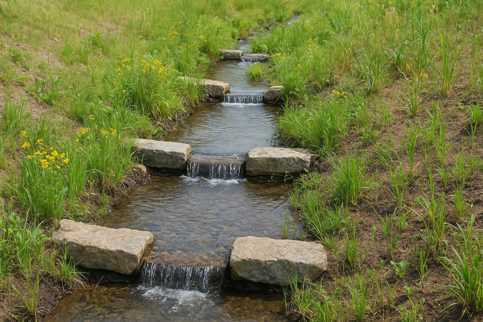
A check dam that overtops unevenly will erode around its edges, so always extend the dam structure into both channel banks by at least 300 mm.
Use rock, timber, or precast concrete based on your flow volume and site context. Rock check dams handle high debris loads, while precast concrete suits narrow channels with defined maintenance access.
Design a safe overflow path
Every bioswale needs a defined overflow route for storms larger than your design event. Route excess flow through one of these options based on your downstream conditions:
- Level spreader: distributes concentrated flow as sheet flow across vegetated ground
- Riprap apron: absorbs energy at the outlet before flow reaches a receiving drain
- Piped bypass: directs excess volume to a downstream detention or discharge point
Step 4. Specify soil, plants, and construction details
The final layer of bioswale design guidelines concerns what goes inside and on top of the channel. Your soil media and planting selection directly control how well the system filters runoff, and construction sequencing determines whether those materials stay in place through the first storm season.
Build the right growing media profile
Your bioswale requires a specified engineered soil mix, not the native soil from your excavation. A standard profile for Malaysian conditions uses a 600 mm deep growing media layer composed of 60 percent washed sand, 20 percent composted organic material, and 20 percent topsoil. This blend balances infiltration capacity with the nutrient retention your plants need to establish.
If your native soil percolation rate from Step 1 falls below 15 mm/hr, install a 100 mm perforated underdrain pipe at the base of the media layer to prevent waterlogging between storm events.
Below the growing media, place a 150 mm gravel transition layer to prevent fine particles from migrating down and clogging the underdrain over time.
Select plants suited to tropical conditions
Your plant selection must handle repeated inundation cycles followed by dry intervals between storms. In Malaysia, prioritize species with deep root systems and demonstrated tolerance for both waterlogging and drought. Vetiver grass (Chrysopogon zizanioides) performs reliably on channel banks, while Heliconia suits wetter zones near the base of the channel.
| Zone | Plant type | Example species |
|---|---|---|
| Channel base | Wetland-tolerant grass | Vetiver, Lemongrass |
| Mid-bank | Moisture-tolerant shrub | Heliconia, Canna lily |
| Upper bank | Drought-tolerant groundcover | Mondo grass, Lily turf |
Follow the correct construction sequence
Your construction order protects each layer from contamination before the next goes down. Place the gravel base first, then the growing media, then install plants before connecting any upstream inflow. Turf or seed all disturbed bank areas immediately after grading to prevent erosion during the plant establishment period.
Next steps for your site
Following these bioswale design guidelines gives you a solid technical foundation, but translating specifications into a finished channel requires careful coordination between your site survey data, engineering calculations, and construction sequencing. Start by completing the site assessment in Step 1 before committing to any dimensions. Your catchment area and native soil percolation results will drive every sizing decision that follows.
Once your design is confirmed, prioritize plant establishment before connecting inflow to the system. A channel with bare soil banks will erode through the first storm regardless of how precisely you sized it. Give vegetation at least four to six weeks to root before directing runoff into the swale.
If your property needs a broader stormwater and landscape water management strategy beyond a single bioswale, our team at Konzept Garden can assess your full site and recommend integrated design solutions tailored to Malaysian conditions. Contact us for a consultation and we will work through the technical details with you.

